


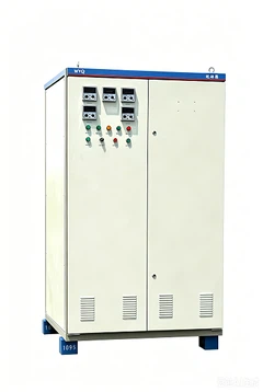


General
This middle voltage switchgear can meet the requirements of GB3906, IEC298 and so on, which has the "five-prevention" functions of preventing the error operation of the circuit breaker, preventing the push-and -pull of the hand drawer on-load, preventing from switching the grounding switch with power on, preventing the power transmission of the grounding switch in grounding position and the power spacer to prevent error entry. This switchgear is truly a power distribution device with super performance, which can adopt VD4 vacuum circuit breaker from ABB Company or VS1 vacuum circuit breaker at home.
Use condition
Environment temperature: -15℃ to +40℃
Relative humidity: daily average ≤95% monthly average≤90%
Height above sea level: ≤1000m
Earthquake magnitude ≤8
No fire, explosion danger, serious pollution, or chemical erosion occasion.
Main characteristics
The structure of the middle voltage switchgear is bolt by aluminum zinc alloy board after the process of CNC machine tool and multi bending technology;
All the operation can be done after the cabinet door is closed;
High protection degree, protect the intruder of sundries and pests;
Simple and effective "five-prevention" lock function, protect error operation;
Can adopt VS1 and CD4 vacuum circuit breaker;
Easy replacement of the circuit breaker and free exchange of the drawers;
The cabinet can be installed by the wall, maintenance in the front, which reduces the floor space;
Large space of the cable room can connect many cables;
The relay room and the cable room can respectively add a heater to avoid freezing or erosion.


Major technical parameters
Major technical parameters of vacuum switchgear
|
No. |
Name |
Unit |
Data |
|
|
1 |
Rated Voltage |
KV |
3,6,10 |
|
|
2 |
Rated Current |
A |
630,1000,1250,1600, 2000,2500,3150,5000 |
|
|
3 |
Rated Frequency |
Hz |
50 |
|
|
4 |
Rated short-time tolerant voltage |
kA |
20, 25, 31.5, 40 |
|
|
5 |
Rated peak tolerant voltage |
kA |
50, 63, 80, 100 |
|
|
6 |
Rated power frequency tolerant voltage |
Inter-polar /polar to ground |
kV |
42/1min |
|
Inter-fracture |
kV |
48/1min |
||
|
7 |
Rated lightening shock tolerant voltage |
Inter-polar /polar to ground |
kV |
75 |
|
Inter-fracture |
kV |
85 |
||
|
8 |
Rated lasting time of short-circuit |
s |
4 |
|
|
9 |
Protection degree |
Shell IP4X, interval room IP2X |
||
Major parameters of vacuum breakers
|
No. |
Name |
Unit |
Data |
|
|
1 |
Rated voltage |
kV |
3, 6, 10 |
|
|
2 |
Rated frequency |
Hz |
50 |
|
|
3 |
Rated current |
A |
630, 1250,1600,2000,2500,3150 |
|
|
4 |
Rated open circuit current when short circuit |
kA |
20,25,31.5,40 |
|
|
5 |
4s hot stable current |
kA |
20,25,31.5,40 |
|
|
6 |
Rated dynamic stable current(peak value) |
kA |
50,63, 80,100 |
|
|
7 |
Rated power frequency tolerant voltage |
Inter-polar /polar to ground |
kV |
42/1min |
|
Inter-fracture |
kV |
48/1min |
||
|
8 |
Rated lightening shock tolerant voltage |
Inter-polar /polar to ground |
kV |
75 |
|
Inter-fracture |
kV |
85 |
||
|
9 |
Rated lasting time of short-circuit |
s |
4 |
|
Order notice
The following materials should be provided by the users when ordering:
1. The scheme no. of the main wiring, diagram of single line system, range diagram and arrangement plan;
2. Wiring diagram of the secondary loop and the diagram of the arrangement of the terminals;
3. The type, specification and quantity of the electric elements of the switchgear;
4. The specification and the material of the main bus bar and the branch bus bar;
5. Quantity of accessories or spare parts;
6. Special requirements need to be negotiated with the factory;
7. Whereas the standard, material, technology requirement and installation dimension in this manual will be developed with the time pass by, our company keeps the rights for adjusting the maintenance information.

Attached
▲structure diagram and overall dimension:

| A Bus bar room | B Hand buggy room of the circuit breaker | C Cable room | D Instrument room of the relay |
| 1.1 Pressure releasing device | 1.2 Control little slot | 1. The shell | 2. Branch bus bar |
| 3. Bus bar bushing | 4. The main bus bar | 5. Static contact device | 6. Static contact box |
| 7. Current transformer | 8. The ground switch | 9. The cable | 10. Lightning arrester |
| 11. Grounding main bus bar | 12. Assembly isolating board | 13. The isolating board | 14. The secondary plug |
| 15. Hand buggy of the circuit breaker | 16. The heater | 17. Withdrawable horizontal isolating board | 18. Operating mechanism of the grounding switch |
| 19. The bottom board |
FAQ