


General
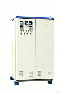
We are KYN28-12 (Z) indoor metal clad medium voltage switchgear manufacturer, It's a set of power distribution device of rated voltage 3 to 12KV three-phase AC 50Hz of single bus bar and single bus bar segmental system. It is applicable to power transmission of the power plant, power receiving and distribution of the electric system and the substation of the industrial enterprises to fulfill the aims of control, protection and inspection.
Major technical parameters
Major technical parameters of vacuum switchgear
|
No. |
Name |
Unit |
Data |
|
|
1 |
Rated Voltage |
KV |
3, 6, 10 |
|
|
2 |
Rated Current |
A |
630, 1000, 1250, 1600, 2000, 2500, 3150 |
|
|
3 |
Rated Frequency |
Hz |
50 |
|
|
4 |
Rated short-time tolerant voltage |
kA |
20, 25, 31.5, 40 |
|
|
5 |
Rated peak tolerant voltage |
kA |
50, 63, 80, 100 |
|
|
6 |
Rated power frequency tolerant voltage |
Inter-polar /polar to ground |
kV |
42/1min |
|
Inter-fracture |
kV |
48/1min |
||
|
7 |
Rated lightening shock tolerant voltage |
Inter-polar /polar to ground |
kV |
75 |
|
Inter-fracture |
kV |
85 |
||
|
8 |
Rated lasting time of short-circuit |
s |
4 |
|
|
9 |
Protection degree |
Shell IP4X, interval room IP2X |
||
Major parameters of vacuum breakers
|
No. |
Name |
Unit |
Data |
|
|
1 |
Rated voltage |
kV |
3, 6, 10 |
|
|
2 |
Rated frequency |
Hz |
50 |
|
|
3 |
Rated current |
A |
630, 1250,1600,2000,2500,3150 |
|
|
4 |
Rated open circuit current when short circuit |
kA |
20,25,31.5,40 |
|
|
5 |
4s hot stable current |
kA |
20,25,31.5,40 |
|
|
6 |
Rated dynamic stable current(peak value) |
kA |
50,63, 80,100 |
|
|
7 |
Rated power frequency tolerant voltage |
Inter-polar /polar to ground |
kV |
42/1min |
|
Inter-fracture |
kV |
48/1min |
||
|
8 |
Rated lightening shock tolerant voltage |
Inter-polar /polar to ground |
kV |
75 |
|
Inter-fracture |
kV |
85 |
||
|
9 |
Rated lasting time of short-circuit |
s |
4 |
|
Instruction of the structure
The medium voltage metal enclosed switchgear is composed of the fixed cabinet body and the drawable part (the drawers). The cabinet shell and the interval boards are all bolt with aluminum zinc alloy boards. The protection degree of the cabinet shell can reach up IP4X, and IP2X of each interval room.
The cabinet has the functions of overhead inlet and outlet, cable inlet and outlet and left-right contact. Arrange the scheme cabinets according to usage to compose a power distribution device which can fulfill the designed function.
The installation and the commission of the switchgear can be done in the front. The cabinet can stand by the wall to save the floor space and lower the investment.


Attached
▲structure diagram and overall dimension:

| A Bus bar room | B Hand buggy room of the circuit breaker | C Cable room | D Instrument room of the relay |
| 1.1 Pressure releasing device | 1.2 Control little slot | 1. The shell | 2. Branch bus bar |
| 3. Bus bar bushing | 4. The main bus bar | 5. Static contact device | 6. Static contact box |
| 7. Current transformer | 8. The ground switch | 9. The cable | 10. Lightning arrester |
| 11. Grounding main bus bar | 12. Assembly isolating board | 13. The isolating board | 14. The secondary plug |
| 15. Hand buggy of the circuit breaker | 16. The heater | 17. Withdrawable horizontal isolating board | 18. Operating mechanism of the grounding switch |
| 19. The bottom board |
FAQ