


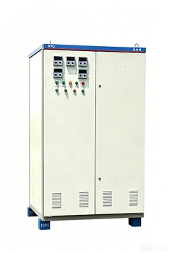


XGN2 Case-style Fixed Metal-Enclosed low & medium voltage switchgear
Generalization
We are low & medium voltage switchgear manufacture, we produced XGN2-10 Case-style Fixed Metal-Enclosed Switchgear (Switchgear) is mainly used as reception and distribution of power supply of 3.6, 7.2 and 12KV, 3Phase AC, 50Hz in indoor system. It is specially applied to cases where frequent operations are needed. The switchgear goes in accordance with State Standard GB3906 and International Standard IEC298 and has strict "five prevention" lock function.

Conditions for use
Environment temperature: -25℃ to +40℃
Relative humidity: daily average ≤95%
monthly average ≤90%
Height above sea level: ≤1000m
No fire, explosion danger, serious pollution, chemical erosion or severe quake.
Earthquake magnitude ≤8
Major technical parameters
Major technical parameters of low & medium voltage switchgear (table 1)
|
No. |
Name |
Unit |
Data |
|||
|
1 |
Rated Voltage |
KV |
3,6,10 |
|||
|
2 |
Rated Current |
A |
630,1000,1250,1600, 2000,2500,3150 |
|||
|
3 |
Rated Frequency |
Hz |
50 |
|||
|
4 |
Rated short-circuit current(valid value) |
kA |
20, 25 |
31.5 |
40 |
|
|
5 |
Rated ripe stable current (peak value) |
kA |
20, 25 |
31.5 |
40 |
|
|
6 |
Rated dynamic stable current(peak value) |
kA |
40 |
80 |
100 |
|
|
7 |
Rated power frequency tolerant voltage |
Inter-polar /polar to ground |
kV |
42 |
||
|
Inter-fracture |
kV |
48 |
||||
|
8 |
Rated lightening shock tolerance voltage |
Inter-polar /polar to ground |
kV |
75 |
||
|
Inter-fracture |
kV |
85 |
||||
|
9 |
Rated thermal time |
s |
4 |
|||
|
10 |
Protection degree |
1P2X |
||||
|
11 |
Outline dimensions |
mm |
1100*1200*2650 (see the note) |
|||
Note: dimensions for high current cabinet: 1200*1200*2650(Bypass bus bar cabinet outline demension1100 (1200*1900*2650(rated current above 2000A, width1200)
Major parameters of vacuum breakers (table2)
|
No. |
Name |
Unit |
Data |
|
1 |
Rated voltage |
kV |
12 |
|
2 |
Rated current |
A |
630,1000,1250,2500,3150 |
|
3 |
Rated frequency |
Hz |
50 |
|
4 |
Rated short-circuit switch off current(valid value) |
kA |
20,25,31.5,40 |
|
5 |
Rated ripe stable current (peak value) |
kA |
20,25,31.5,40 |
|
6 |
Rated short-circuit switch on current (peak value) |
kA |
40,50,80,100 |
|
7 |
Rated peak value tolerance current (peak value) |
kA |
40,50,80,100 |
|
8 |
Rated power frequency tolerance voltage |
kV |
42/1min-Inter-polar polar to ground; 48/1min-Inter-fracture |
|
9 |
Rated lightening shock tolerance voltage |
kV |
75-Inter-polar polar to ground; 85-Inter-fracture |
|
10 |
Rated short-circuit last time |
S |
4 |
|
13 |
Rated capacitance groups switch off current |
A |
630 |
|
14 |
Rated back to back capacitance group switch off current |
A |
400 |
|
15 |
Times of rated short-circuit switch off current |
time |
30 |
|
16 |
Mechanical life |
time |
10000 |
Structure characteristics
- This switchgear is case metal-enclosed structure. In accordance with the national standard GB3906 and international standardIEC298, protection degreeIP2X. The metal-enclosed structure effectively prevents short-circuit failure by intruders and human body from touching the electrical and operating components.
- There are two structures of the cabinet :(1)steel angle welding (2)sectional bar assembling. Inside the cabinet, there are rooms for breaker, bus bars, cables and relay. Iron plates separate each room.
Breaker room is at the bottom of the cabinet with a pressure release channel. If there is any electric arc inside, gas pressure can be released through the channel.
Bus bar room is at the upper back of the cabinet. These lines are supported by epikote insulators (≥8000N). The main bus bar is connected with terminals of the upper insulation switch.
Cable room is at the lower back of the cabinet. Cables are fixed on the stands. This room serves as a communicator when the main connection line is designed to be communication-oriented.
- Any forms of polar to polar or polar to ground insulation boards (or compound insulation) are not applied. When air insulation distance between polar to polar or polar to ground ≤125mm, porcelain support insulators (≥8000N) is applied. All these ensure higher insulation intensity and stability.
-
Breakers, both upper and lower insulation switches, grounding switches and interlock mechanisms between doors all takes force mechanical lock mode to meet the requirement of "five- prevention".
- Double maintenance, not standing by walls. The checking of the second components, maintaining of the operation mechanics/interlocks/transmission parts/breakers is in the front. While the maintenance of the bus bar and cable rooms is in the back. Lighting is available for observation inside the cabinet. Copper bus bars for grounding below the doors are parallel to the width of the cabinet.
The product meets the demand for strict Conditions I. useable in the occasion of frequent freezing and little dirt.

The structure of the typical scheme of the switchgear and the overall dimension

| 1 bus bar room | 2 pressure release channel | 3 meter room |
| 4 combined switch room | 5 manual operation and interlock mechanics | 6 the main switch room |
| 7 electromagnetic or spring mechanics | 8 grounding bus bars | 9 cable room |
FAQ