




General
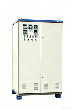
As KYN28-12 mv cubicle manufacturer, Worldwide Electric is located in Xiangyang City, Hubei Province, a famous historical and cultural city in China. It covers an area of over 200000 square meters and has a total investment of 100 million dollars. It consists of three sub projects: electrical energy-saving product project, optoelectronic product project, and mechanical processing project. KYN28-12 mv cubicle is a set of power distribution device of rated voltage 3 to 12KV three-phase AC 50Hz of single bus bar and single bus bar segmental system. It is applicable to power transmission of the power plant, power receiving and distribution of the electric system and the substation of the industrial enterprises to fulfill the aims of control, protection and inspection.
Use condition
Environment temperature: -15℃ to +40℃
Relative humidity: daily average ≤95%
monthly average ≤90%
Height above sea level: ≤1000m
Earthquake magnitude ≤8
No fire, explosion danger, serious pollution, or chemical erosion occasion.
Major technical parameters
Major technical parameters of vacuum switchgear
|
No. |
Name |
Unit |
Data |
|
|
1 |
Rated Voltage |
KV |
3,6,10 |
|
|
2 |
Rated Current |
A |
630,1000,1250,1600, 2000,2500,3150 |
|
|
3 |
Rated Frequency |
Hz |
50 |
|
|
4 |
Rated short-time tolerant voltage |
kA |
20, 25, 31.5, 40 |
|
|
5 |
Rated peak tolerant voltage |
kA |
50, 63, 80, 100 |
|
|
6 |
Rated power frequency tolerant voltage |
Inter-polar /polar to ground |
kV |
42/1min |
|
Inter-fracture |
kV |
48/1min |
||
|
7 |
Rated lightening shock tolerant voltage |
Inter-polar /polar to ground |
kV |
75 |
|
Inter-fracture |
kV |
85 |
||
|
8 |
Rated lasting time of short-circuit |
s |
4 |
|
|
9 |
Protection degree |
Shell IP4X, interval room IP2X |
||
Major parameters of vacuum breakers
|
No. |
Name |
Unit |
Data |
|
|
1 |
Rated voltage |
kV |
3, 6, 10 |
|
|
2 |
Rated frequency |
Hz |
50 |
|
|
3 |
Rated current |
A |
630, 1250,1600,2000,2500,3150 |
|
|
4 |
Rated open circuit current when short circuit |
kA |
20,25,31.5,40 |
|
|
5 |
4s hot stable current |
kA |
20,25,31.5,40 |
|
|
6 |
Rated dynamic stable current(peak value) |
kA |
50,63, 80,100 |
|
|
7 |
Rated power frequency tolerant voltage |
Inter-polar /polar to ground |
kV |
42/1min |
|
Inter-fracture |
kV |
48/1min |
||
|
8 |
Rated lightening shock tolerant voltage |
Inter-polar /polar to ground |
kV |
75 |
|
Inter-fracture |
kV |
85 |
||
|
9 |
Rated lasting time of short-circuit |
s |
4 |
|
Instruction of the structure
The medium voltage metal enclosed switchgear is composed of the fixed cabinet body and the drawable part (the drawers). The cabinet shell and the interval boards are all bolt with aluminum zinc alloy boards. The protection degree of the cabinet shell can reach up IP4X, and IP2X of each interval room.
The cabinet has the functions of overhead inlet and outlet, cable inlet and outlet and left-right contact. Arrange the scheme cabinets according to usage to compose a power distribution device which can fulfill the designed function.
The installation and the commission of the switchgear can be done in the front. The cabinet can stand by the wall to save the floor space and lower the investment.
The cabinet body
The body and the interval boards of the cabinet are bolt by aluminum zinc alloy board after the process of CNC machine tool and multi bending technology, so that the cabinets assembled can guarantee the unity of the structure and the dimension. The aluminum zinc alloy board has the functions of corrosion resistance and oxidation resistance, and has the higher mechanical robustness than the ordinary steel board. The cabinet is divided to drawer room, bus bar room, cable room and relay instrument room by the interval boards with each unit grounding separately. The doors of the cabinet are all handled with the technology process of electrostatic gunning to make the surfaces have the advantages of anti-impaction, corrosion resistance, and beauty and so on.

The drawer
The drawers can be classed to circuit breaker drawer, voltage transformer drawer, metering drawer, separation drawer and station used variety drawer according to different usage. The drawers with the same usage can exchange each other. The drawers have test/separating and working positions inside the cabinet, each position with an interlock unit to ensure the drawers can't move freely in the above two positions.

Circuit breaker drawer room
A special channel has been installed in the isolation room to provide the drawer to move. When the circuit breaker is moving between the test position and the working position, the separating valve automatically opens or closes to ensure that the operating staff can't get in touch with the charged body. The drawers can be operated in the condition that the cabinet door is closed. The position where the drawer is inside the cabinet can be seen through the monitoring window, and any of the labels on the drawer can also be seen. All these guarantee the safety of the operating and the maintenance staff.

The installation of the switchgear (see the attached diagrams)
The construction of the basis of the switchgear shall conform to the relative specification of "technology specifications of electric power construction and inspection".
The installation basis of the switchgear needs to water the concrete twice. The first time to water the concrete is for the installation components of the switchgear that is for the angle steel, square steel or the installation basis of the channel steel. The second time is to water the additional layer of the concrete, usually 60mm in thickness. The height of the concrete shall be 1 to 3mm lower than the surface of the component when water the additional layer of the concrete.
See the attached diagrams for the basic structure frame.
The installation quality shall be ensured when install the basic structure frame. The technology standard of the installation of the structure frame is 1m2 with 1mm tolerance.
See the attached diagrams for the installation basis and installation dimension of the switchgear.
When the cabinet body is unistrand, the passage before the cabinet is 2.5m for the best and 3m when biserial.
Transport the switchgear to the certain place according to the need of the project and the indication of the diagram. If arrange a long line of cabinets (more than 10 sets), the arrangement work shall be started from the middle.
Use special transportation vehicles such as cranes or forklifts. Rollers and crowbars are prohibited.
Take out the drawer of the circuit breaker inside the cabinet; put it in another place for good care.
Loosen the switch to move away the cable cover.
Move away the cover from the control slot on the left side of the cabinet. The cover of the control slot on the right front side shall be moved away in the same way.
Disboard the lifting board and the fastener.
Install the cabinets in sequence on the above basis. The installation plainness of the switchgear shall not exceed 2mm both in horizon position and in vertical position.
When finish the switchgear assembly, it can be connected with the basic structure frame by ground crews or welded by electro-welding.
The bus bars in the switchgear are all segmental square bus bars. Only the quantity and the specification of the bus bar are different when different current has been chosen, thus the following installation processes have to be followed:
Clean the bus bar with a soft clean and dry cloth; check if the isolation bushing is damaged; coat the connecting parts with some conducting cream or neutral Vaseline.
Install the bus bar one cabinet after one cabinet; connect the bus bar section with the corresponding branch small bus bar and insert proper pads when bolting; fasten it with screws.
Connect the grounding bus bar of each cabinet on the preinstalled connecting board;
Connect all the grounding lead inside the cabinet;
Connect the basic structure with the grounding terminals;
Connect the grounding line of the grounding knife switch with the main grounding bus bar of the distribution plate.
Example of the scheme application (see the attached diagram)

| A Bus bar room | B Hand buggy room of the circuit breaker | C Cable room | D Instrument room of the relay |
| 1.1 Pressure releasing device | 1.2 Control little slot | 1. The shell | 2. Branch bus bar |
| 3. Bus bar bushing | 4. The main bus bar | 5. Static contact device | 6. Static contact box |
| 7. Current transformer | 8. The ground switch | 9. The cable | 10. Lightning arrester |
| 11. Grounding main bus bar | 12. Assembly isolating board | 13. The isolating board | 14. The secondary plug |
| 15. Hand buggy of the circuit breaker | 16. The heater | 17. Withdrawable horizontal isolating board | 18. Operating mechanism of the grounding switch |
| 19. The bottom board |
FAQ